EKATO
Conventional Impellers
For Axial, Radial and Tangential Flow
In mixing technology, a large variety of impellers is used for a wide range of applications. The various designs can be traced back to a few basic types. The dimensions and designations of these are standardized in DIN 28131.
Table of Contents
In principle, it is useful to categorize agitators according to the following aspects
- Primary flow direction: axial, radial or tangential
- Close to the wall and central operating impellers
- Tip speed
- Viscosity range or flow regime: laminar, turbulent or transitional
In practice, impellers are usually classified according to the primary flow direction. In addition to the desired axial or radial flow, each agitator also generates a tangential flow through the transmission of the rotary movement to the liquid. A three-dimensional flow thus prevails in a mixing vessel. This flow field is strongly influenced by components in the container. Undesired tangential flow in the stirring system can often be reduced by the installation of baffles on the vessel wall.
Axial Flow Impellers
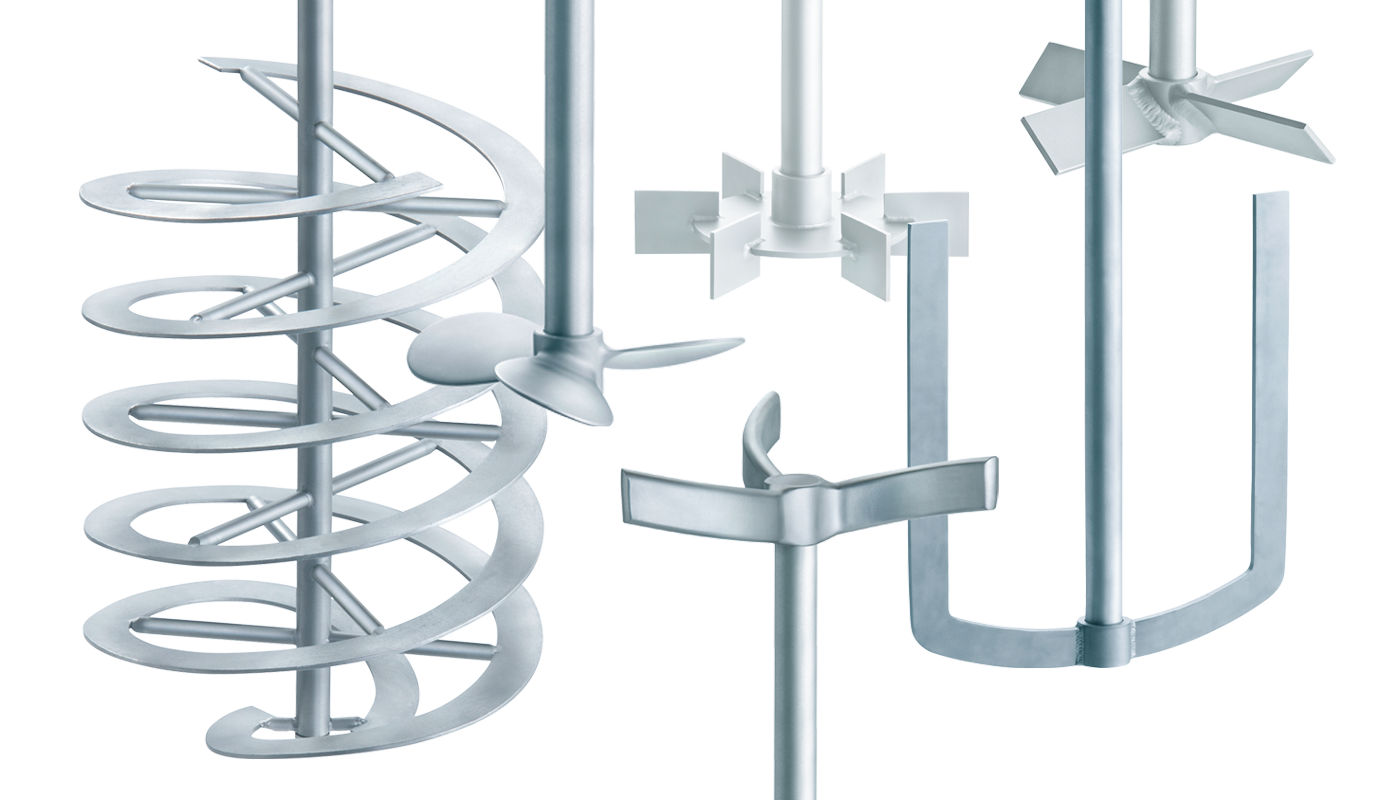
Propeller
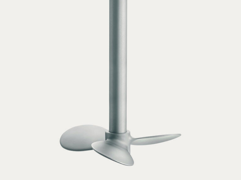
A typical axial pumping impeller for low viscosity media is the three-bladed propeller. This versatile impeller is particularly suitable for homogenizing and suspending. The flow pattern shows a strong axial suction and a strongly bundled discharge stream in the turbulent flow range. The outlet jet-stream is deflected at the bottom and reaches the surface in the wall area of the vessel. The liquid is accelerated in the area of the propeller.
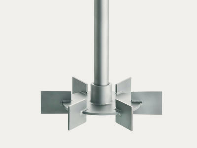
Pitch blade turbines
A roughly comparable flow pattern is produced by the four-bladed pitch blade turbine with a blade angle of 45°. However, a stronger radial component is formed. Opposite the propeller, the application area is extended; viscosities of up to 20,000 mPa s can be processed. The application range thus extends to the laminar as well as the turbulent flow regime, but the efficiency is relatively low because of the very simple blade shape.
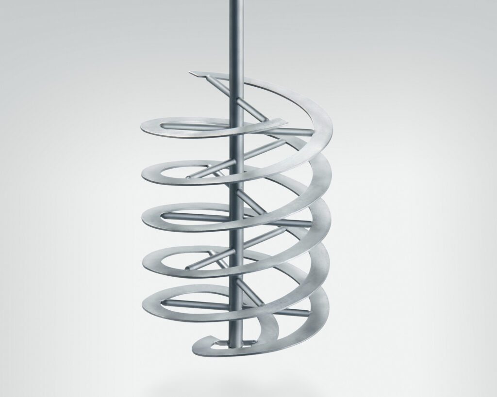
Helical ribbon impellers
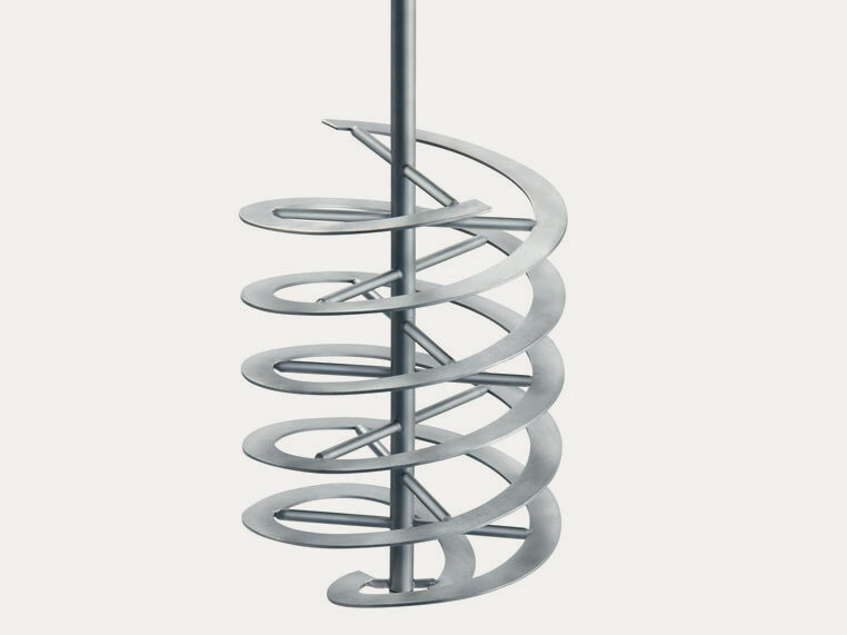
The helical ribbon impeller is suitable for homogenizing highly viscous media. It consists of a band-shaped helix which is fixed to the shaft by cross-bars. In contrast to the propeller, the axial flow is not caused by pressure differences, but by a displacement effect in the laminar flow regime. One disadvantage of the helical ribbon impeller is the mandatory use of crosspieces for stabilization. These prevent the installation of baffles, dip tubes, etc. which may be beneficial or necessary in many practical applications. With a diameter ratio of 0.9 to 0.99, the helical ribbon impeller is a close to the wall operating impeller.
Radial Flow Impellers
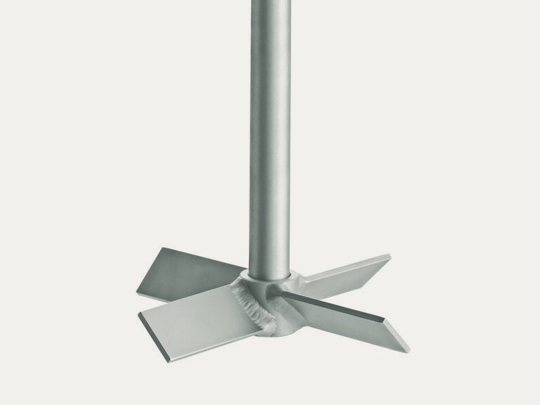
Rushton disc turbine
A representative of the radially pumping impellers commonly used is the Rushton disc turbine. Several (usually six) vertical rectangular blades are arranged symmetrically along the circumference on a horizontally arranged carrier disc. The the flat blade disc turbine is mainly used for gassed applications. In this case, the disadvantages of this impeller are a relatively low flooding limit as well as a high power decrease. An extension to further mixing tasks is only possible under certain conditions. With this impeller, the actual mixing effect predominantly occurs in the shear zone of the radial outflow.
Retreat curve impellers
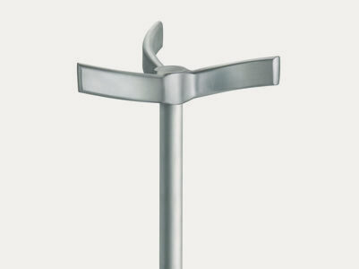
The retreat curve impeller is a relatively fast-running impeller with (usually) three blades bent backwards in the direction of flow. The main flow direction is radial. The amount of axial flow depends on the diameter ratio and the bottom clearance of the impeller. The retreat curve impeller is usually operated together with one or two finger-shaped baffles in the mixing system for homogenizing and improving heat transfer in liquids with a generally low viscosity. However the suitability is limited. Because the shape of the retreat curve impeller is originally designed for glass-lined applications, it is not optimal in terms of fluid dynamics and is therefore increasingly being replaced by more efficient impellers.
Tangential Flow Impellers
Anchor impeller
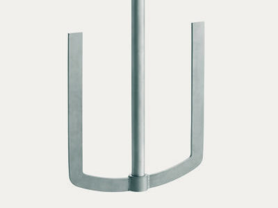
A typical representative of impellers with tangential flow is the anchor which generally consists of two blades arranged parallel to the shaft. These are connected via a cross bar following the contour of the vessel bottom. With a diameter ratio of 0.9 to 0.99, the anchor impeller has a small wall clearance. Its main task is to reduce the thickness of the highly viscous boundary layer adhering to the vessel wall in order to intensify the heat exchange. Finger or frame impellers which are still used occasionally, have properties similar to anchor impellers.